|
CONFIDENTIAL TECHNICAL REPORT
_____________ WAR DAMAGE REPORT --U.S.S. FRANKLIN (CV 13)
ACTION OF OCT.,30, 1944. DATE
PUGET SOUND NAVY YARD INDUSTRIAL DEPARTMENT SCIENTIFIC & TEST GROUP CODE 274
|
|
WAR DAMAGE REPORT -- U.S.S. FRANKLIN (CV13)
1. The U.S.S. Franklin was steaming at 18 knots in an area about 100 miles East of Samar Island, P.I. on 30 October 1944. At 1426 the ship was attacked by Japanese planes. Shortly afterward the ship was struck on the Flight Deck by a plane and its bomb load. The plane hit at frame 127 about 20 feet starboard of centerline as nearly as can be determined, and penetratod the Flight Deck. It is not known whether one or two bombs were carried by the plane; however, the force of the explosion was estimatod to be equivalent to that produced by a 500 lb. G.P. bomb. It is believed that the bomb load exploded at the Gallery Deck level. The condition of the ship at the time of the attack and the measures taken to maintain military efficiency and seaworthiness are described in the ships report, reference (a). The damage due to the explosion and fire, as determined by the Yard from an inspection of the vessel and discussion with the ship's personnel, is described in this report.
- 2 -
|
|
WAR DAMAGE REPORT -- U.S.S. FRANKLIN (CV13)
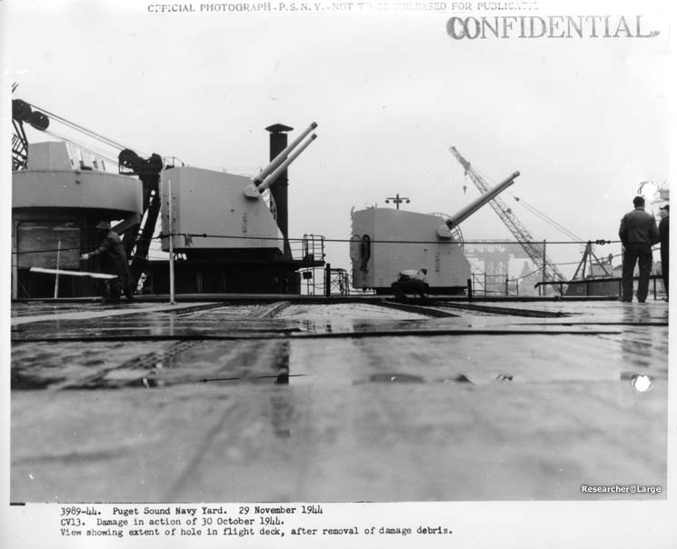
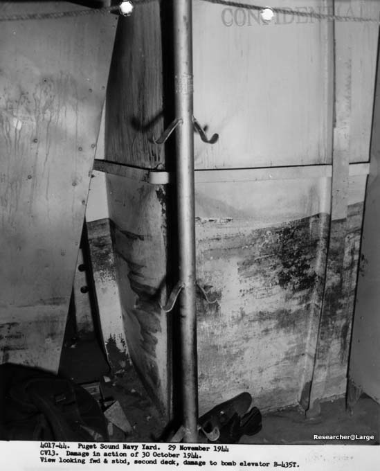
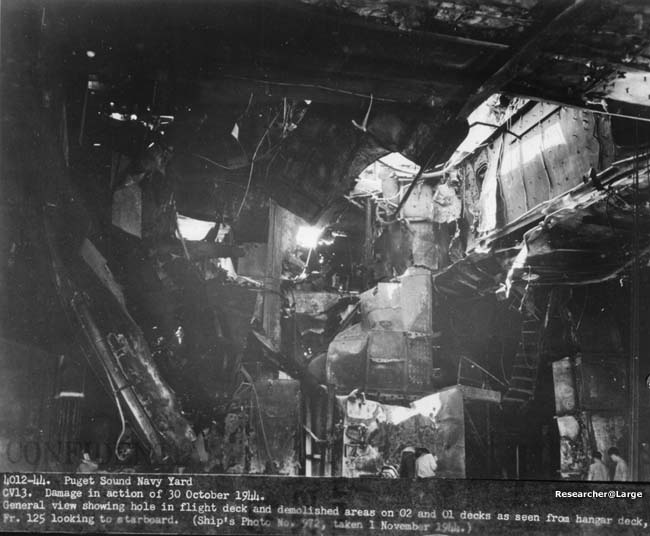
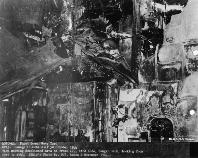
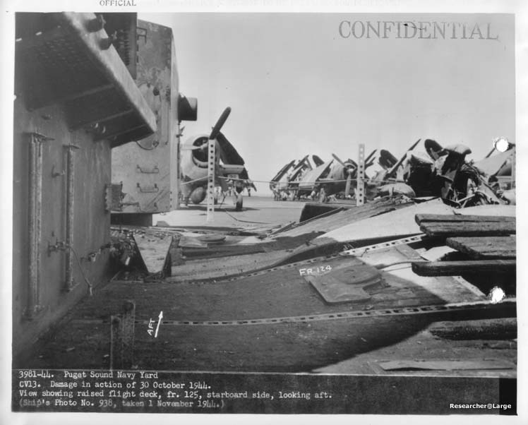
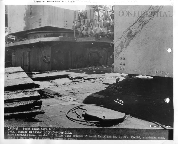
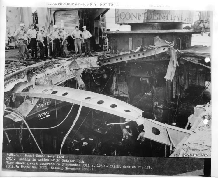
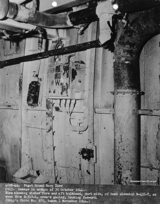
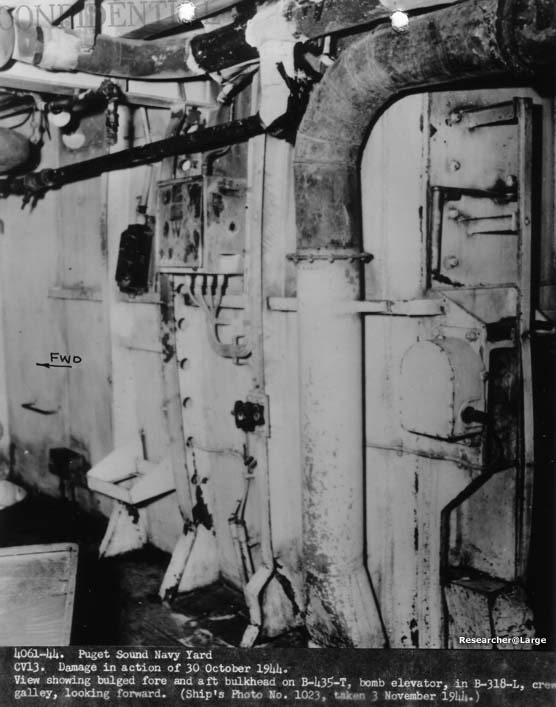
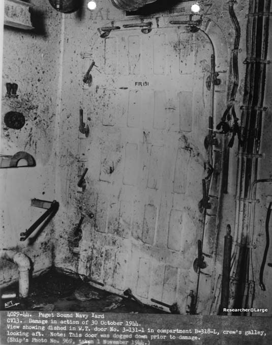
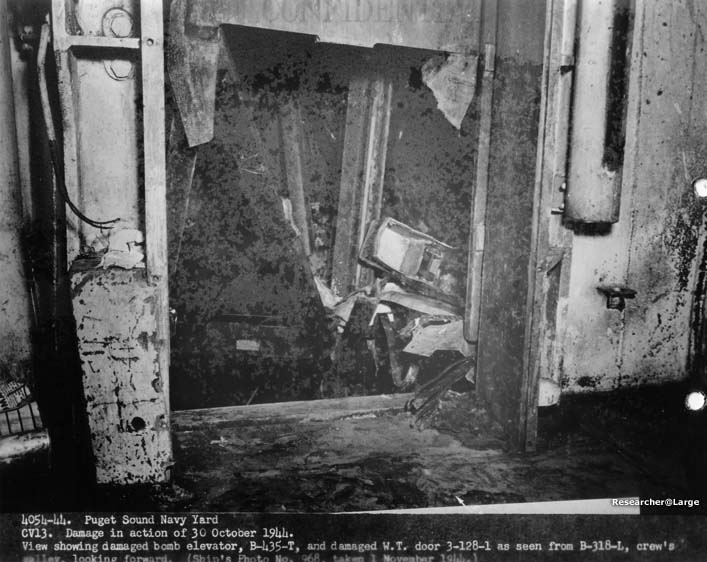
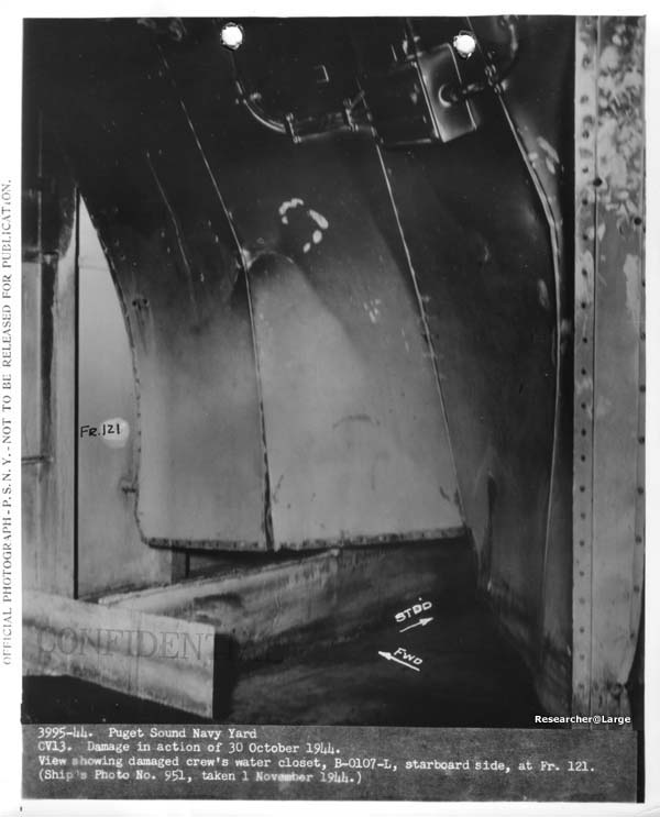
Section II Structural 1. The Japanese plane, carrying one or two instantaneously fuzed bombs, penetrated the Flight Deck to the Gallery Deck level and exploded, causing severe structural damage in the immediate vicinity and starting gasoline fires among the planes parked on the Hangar Deck. 2. The Flight Deck plating was holed by the impact of the plane, and dished upward and buckled by the blast been frames 125 and 128, port, and frames 121 and 130 starboard. Structural bulkheads 125 and 128, although severely damaged, confined the explosion and reduced the fore and aft extant of the blast damage to the area between frames 121 and 131. Longitudinal Gallery Deck structural bulkheads between frame 121 and 131 were demolished or buckled (see Appendix "B"). The blast ruptured the starboard Hangar side plating at frame 127 just below the Flight Deck. The Gallery Deck plating in way of the explosion was demolished and buckled between frames 121 to 142 (Port) from the intense heat generated by gasoline fires on tha Hangar Deck. Transverse Flight Deck supporting girders at frames 113, 117 and 121 were warped slightly by the fire. (See Photos #3980-44 to 3995-44 incl., 4003-44 to 4007-44 incl., 4012-44 and 4016-44.) 3. Although blast damage to the adjacent Flight Deck Plating and Gallery Deck bulkheads was severe, the effect on the principal foundation bulkheads supporting 5"/38 mounts nos. 5 and 7 was slight. An examination by this Yard disclosed no misalignment or binding in the mount, that might have directly resu1ted frou distortion of the foundation. (See photos #3981-44, 3983-44s 3984-44s, 4012-44 and 4016-44.) 4. There was no evidence of damage to the Hangar Deck plating and beams; there were only a few isolated fragment holes in bulkheads in the Hangar space. The bomb elevator trunk was demo1ished from the Flight Deck to Forecastle Deck and severely buckled and distorted from the Forecastle Deck to the Hangar Deck. (See photos #4012-44 and 4016-44.) 5. Blast from the explosion on the Gallery Deck traveled down the bomb elevator trunk to the 4th Deck, causing the trunk bulkheads to be dished out about 5 inches maximum midway between decks. The only apparent sign of rupture in these bu1kheads was a crack or weld failure at the corners of the trunk in way of the horizontal stiffeners and extending about 3 inches above and below the web of the stiffener. (See photos #4017-44, 4028-44, and 4061-44) Blast escaping through the bomb elevator door on the 3rd Deck damaged a short section of bulkhead 131 and a door in the bulkhead. (See photos #4029-44 and 4054-44.) 6. The ship reported that after the bomb exploded on the Gallery Deck two separate explosions on the 3rd Deck occured, one in compartment B-319L and the other in compartment B-324L. Investigation of the resulting damage by the Yard also revealed the possibility of an explosion centering in compartment B-313E, undetected by the ship and, therefore, not mentioned in the ship's reports. The explosions presumably originated from the ignition of gasoline
- 3 -
|
|
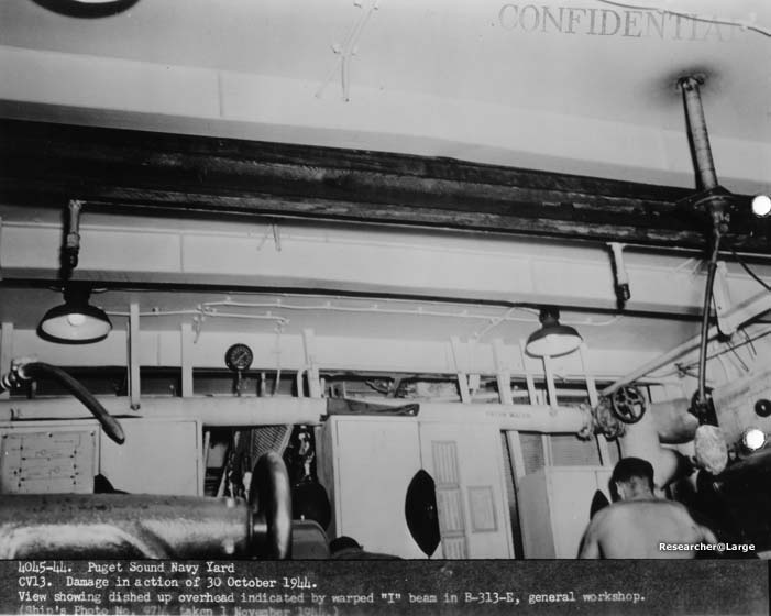
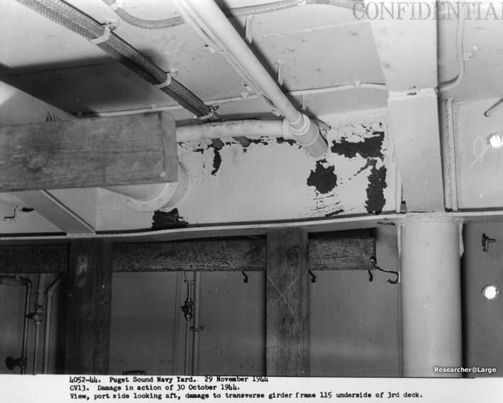
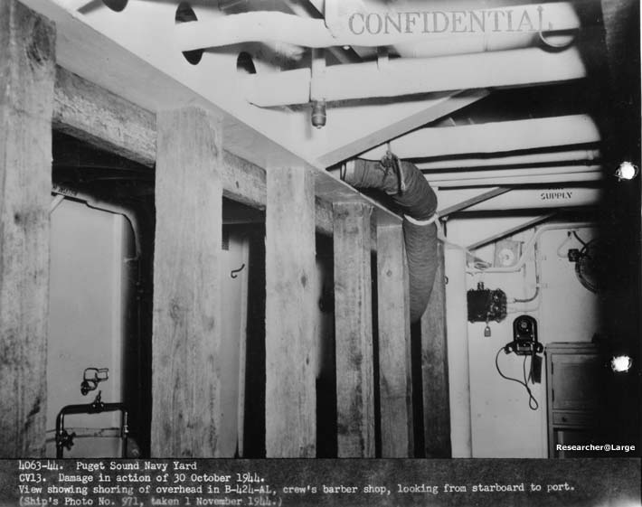
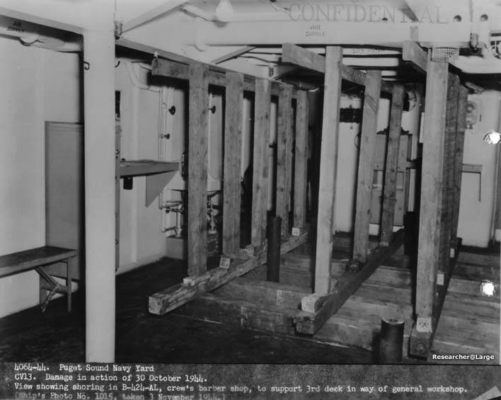
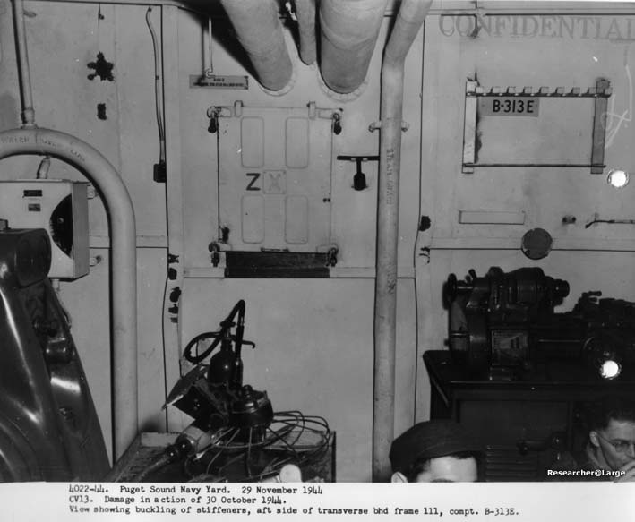
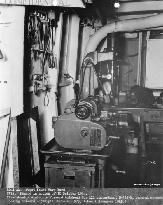
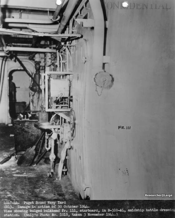
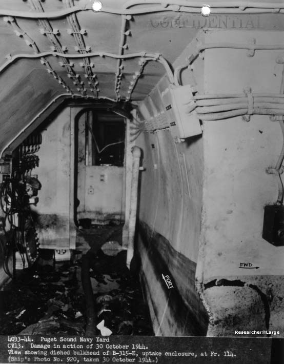
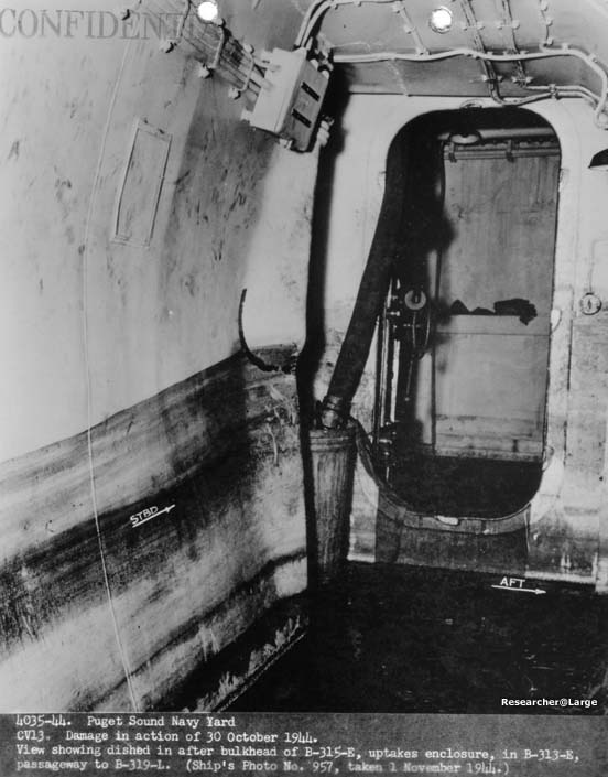
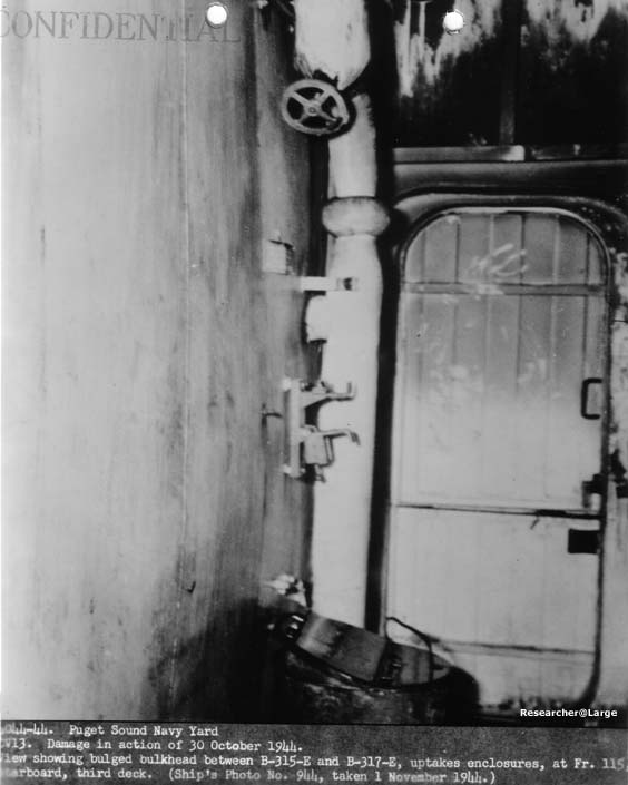
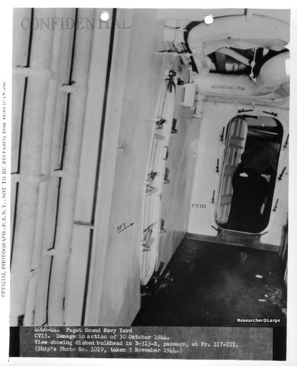
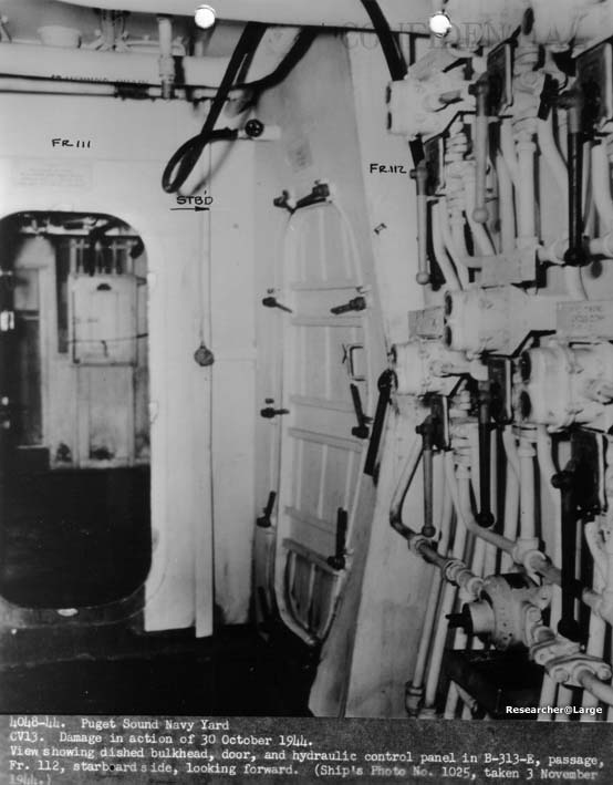
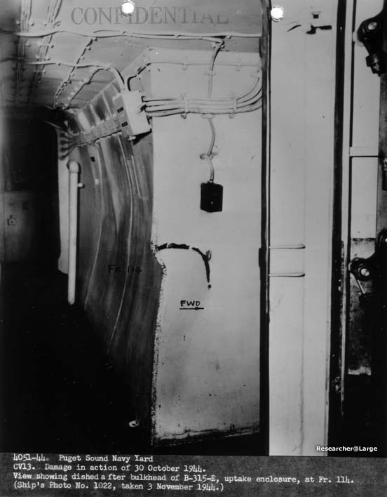
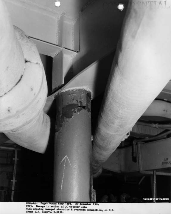
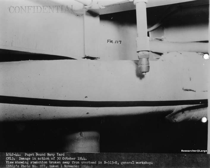
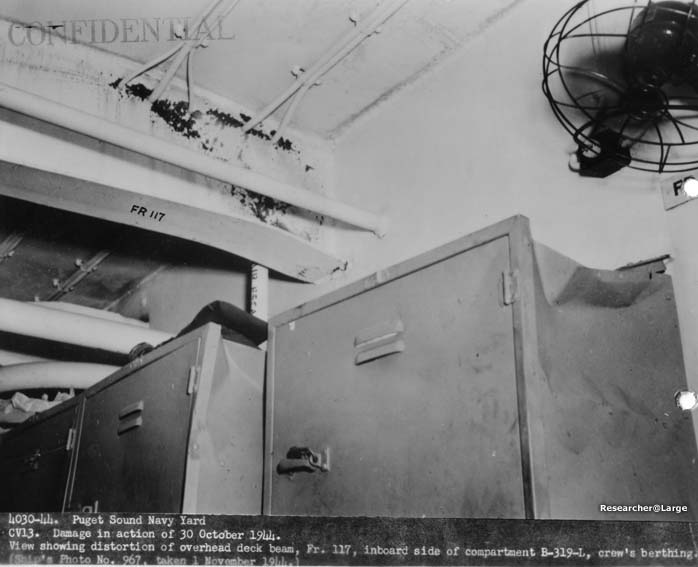
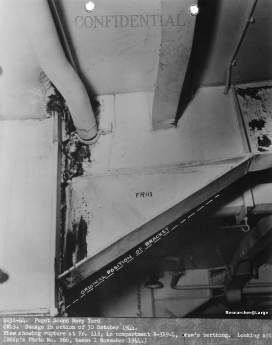
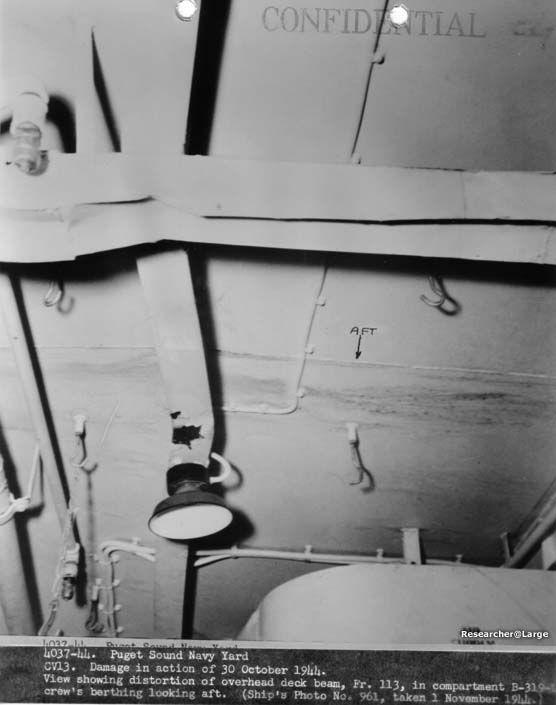
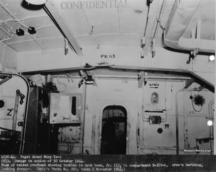
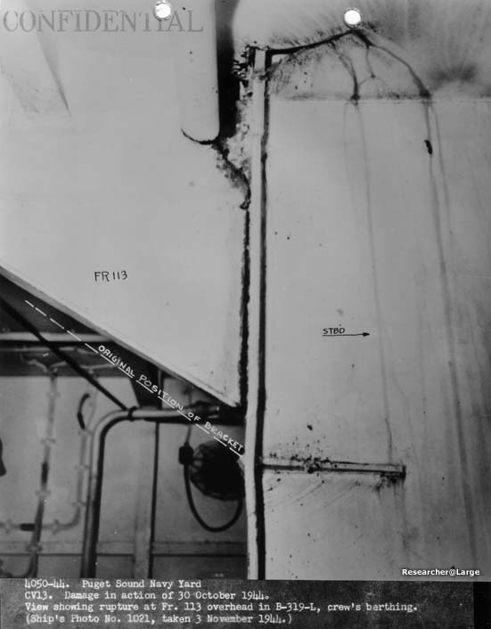
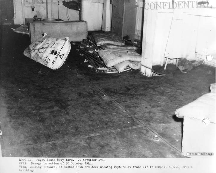
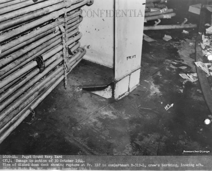
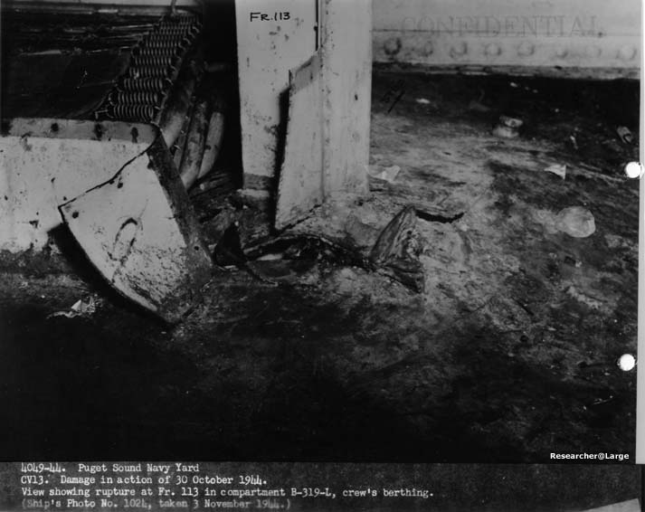
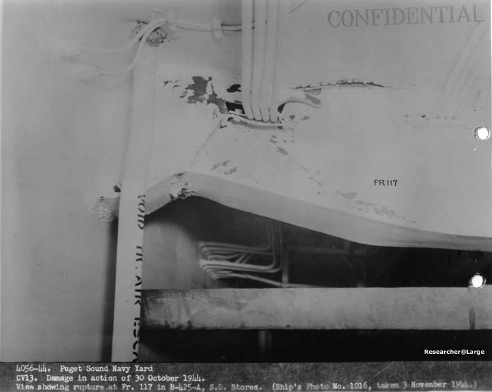
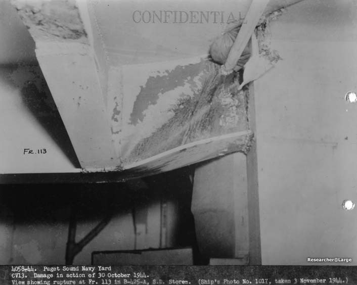
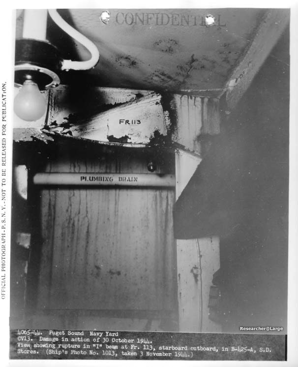
vapors accumulated in these spaoes. 7. The explosion in compartment B-313E dished the 2nd and 3rd Decks, with a maximum deflection on each deck approximately 2 1/2 inches at frame 115 port. The 2nd and 3rd deck transverses and longitudinal beams sustained a permanent deflection but no pronounced distortion or buckling. (See photos #4045-44, 4052-44, 4052-44, 4063-44, and 4064-44.) The explosion caused a slight buckling of stiffeners on bulkhead 111 (see photos #4022-44, 4041-44, and 4047-44) and dished the inboard longitudinal uptake enclosure bulkheads, frame 111 to 121, and tranverse uptake enclosure bulkhead 114 Ľ. (See photos 4033-44, 4035-44, 4036-44, 4044-44, 4046-44, 4048-44, and 4051-44.) It is interesting to note the nature of the tension failure of the connection at the top of the centerline stanchion on frame 117, since this structureal member is usually designed to withstand a compression loading. (See photos 4024-44 and 4042-44.) 8. The explosion in compartment B-319L dished tho 2nd and 3rd Decks, producing a maximum deflection of about 12 inches in both decks. Transverse 113 and 117 under the 2nd Deck were wrinkled and distorted, showing definite failure due to excessive shearing and bending stresses in the girder. It should be noted that the shearing failure of the welded connection of the girder bracket to the face plate of web 113 under the 2nd Deck indicates either poor welding or insufficient weld metal to develop the full strength of the bracket. It is significant that the only rupture of the deck plating occurred in way of this shear failure of the beam end. (See photos #4030-44, 4031-44, 4037-44, 4038-44, and 4050-44.) Structural failures in the 3rd Deck transverse girders were very similar to those in the 2nd deck transverses. There were vertical shear failures at girder ends and also diagonal wrinkles in the web at the end of each girder, indicating a failure and deflection due to diagonal shear. (See photos #4025-44, 4026-44, 4049-44, 4056-44, 4058-44, and 4065-44.) The inboard longitudinal and transverse bulkheads, bounding compartments B-319L, suffered only slight damage from the explosion. The expanding gases blew off the watertight door on bulkheads 111 and 121, and escaped into compartments B-311L and B-323L. 9. The explosion in compartment B-324L caused no appreciable structural damage; however, some lockers were smashed and tables thrown about. 10. Fires in compartments below the Hangar Deck caused very little if any structural damage. Open hatches on the Hangar Deck that could not be closed due to the fire in the Hangar Space, permitted water and gasoline to flood the lower decks. 11. In general, the structural damage had a minor effect on the ship's strength.
- 4 -
|
|
WAR DAMAGE REPORT -- U.S.S. FRANKLIN (CV13)
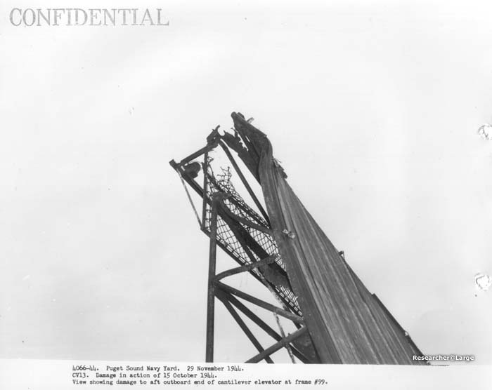
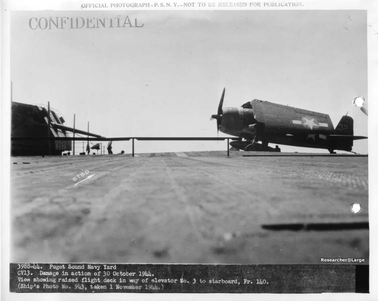
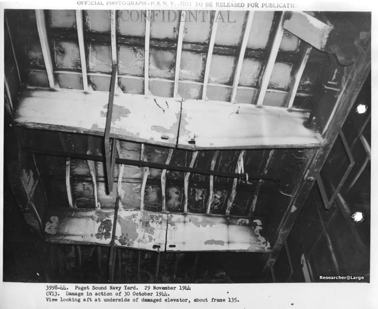
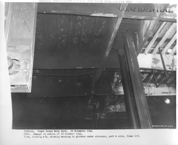
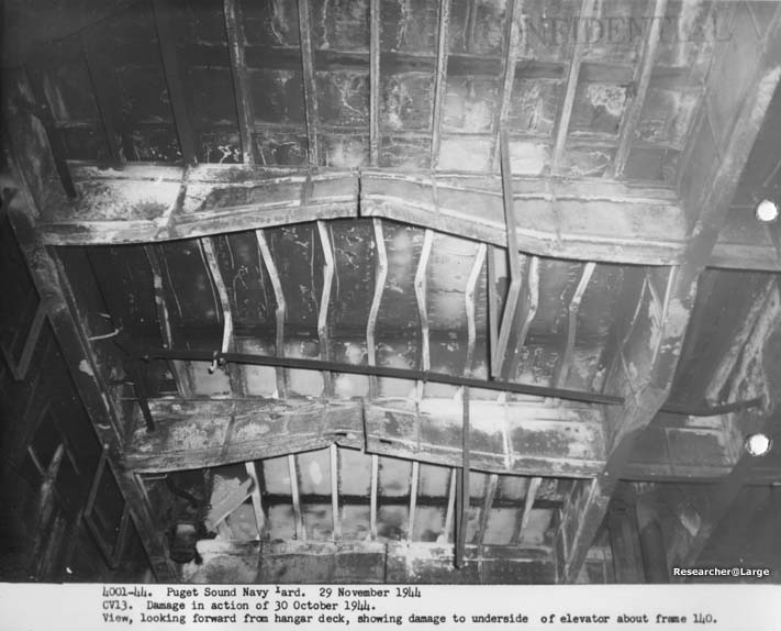
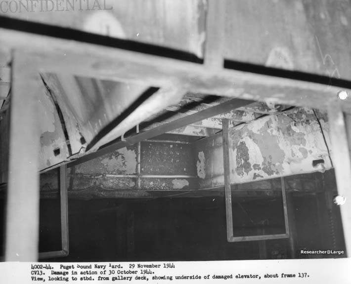
Section III Hull Fittings 1. As a result of the attack, two important items under the classification of hull fittings were damaged. The midship plane elevator was bulged upward by the bomb explosion (see photos nos. 3988-44, 3998-44, 3999-44, 4001-44 and 4002-44), and the bomb elevator trunk severely distorted by explosion of gasoline vapor, which was admitted to the bomb elevator through open doors on the Hangar Deck.
- 5 -
|
|
WAR DAMAGE REPORT -- U.S.S. FRANKLIN (CV13)
Section IV Piping 1. Damage to piping systems was not extensive; however, a brief description of the systems affected and pertinent comments follows. 2. In the immediate vicinity of the hit, compressed sir system, steam heating system, fresh water system, aviation lub. oil system, and plumbing drains were damaged by explosion and fire. The ruptured portions of these systems were readily isolated by cut-out valves. 3. A gasoline station on the Flight Deck was damaged by fire, and a gasoline hose burned on the Hangar Deck. No evidence of explosion was observed around the gasoline stations or piping. No design changes are recommended that offered in the "P.S.N.Y. War Damage Report on CVE27" in which it was suggested that the gasoline hose be stored inside the fume tight box with the filters and the defueling pump.
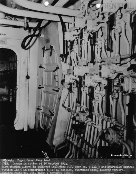
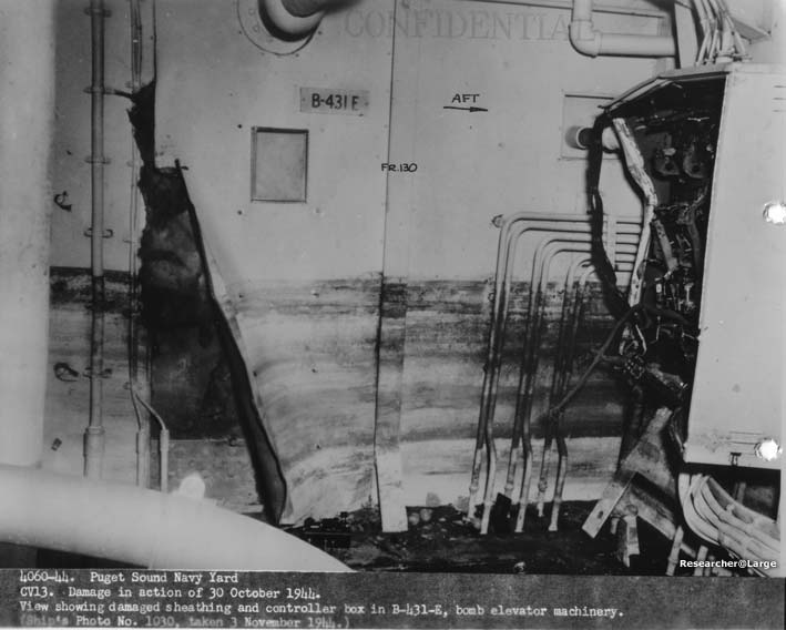
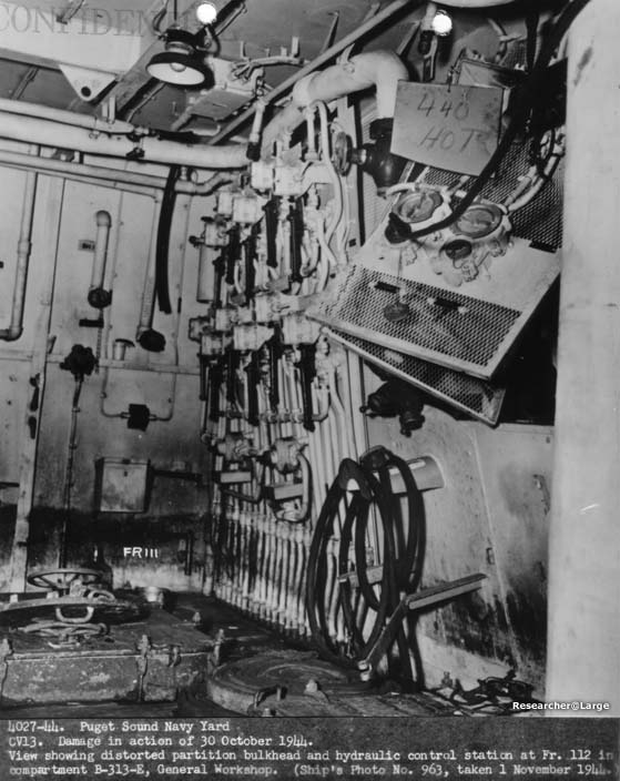
4. (a) Damage to a firemain riser caused the loss of use of six fireplugs, sprinkling for compartments B-0219M and B-0315M, and one foam generator. The presence of dense smoke and fire on the damage control deck prevented use of cut out valves through which three additional fire plugs could have been returned to service. The part of the system affected by this damage was designed to permit isolation of the damaged portions, and is considered satisfactory as installed. 5. Refernce (a) states that about 2000 tons of water from Hangar sprinklers and hoses collected on the Hangar Deck and decks below. A large part of the water came from the Hangar sprinkling system. The sprinkling and water curtain system cools the area in which it operates but does not extinguish gasoline fires. The FRANKLIN had standard commercial heads for sprinklers and S-1 and S-2 type sprinkler heads for water curtains. It is understood that for cooling, water in the form of fog is most effective. With this in mind, the Yard suggests that a more efficient Hangar Deck sprinkler system may be obtained by the use of L-11 fog heads in lieu of the comercial sprinkling heads, and high velocity fog heads properly spaced and directed downward in lieu of the S-1 and S-2 heads now installed in the water curtains. It is believed that equal or greater cooling may be obtained in this manner with a substantially reduced quantity of water. This would relieve the firemain system of excessive load and alleviate, to some extent, the problem of disposal of the large quantities of water now released in the Hangar Deck space by the sprinkling system (see section IX). It is believed that the high velocity fog heads would form an effective water curtain. If the L-11 heads are not considered suitable for mounting 18 feet above the deck, it is believed that fog heads could be developed for this service. 6. The hydraulic valve control system showed exceptional resistance to damage. None of the installations was put out of order, although the panel in B-331E just
- 6 -
|
|
outboard ot the general workshop, frames 111 to 114, port, was tipped outboard about 30° by one of the explosions.
- 7 -
|
|
WAR DAMAGE REPORT -- U.S.S. FRANKLIN (CV13)
Section V Ordinance 1. Damage to ordinance was slight. Sights on the 5"/38 Cal. Twin Gun Mounts Nos. 5 and 7 were overheated by fire and required a general cleanup and overhaul.
- 8 -
|
|
WAR DAMAGE REPORT -- U.S.S. FRANKLIN (CV13)
Section VI Radar and Radio 1. Radar equipment on the Gallery Deck between frames 79 to 96 suffered damage due to fire, and to salt water from fire fighting activities. A number of units were also put out of comission by shock from the bomb explosion. 2. The SM spare console, OZ tube tester and two LW frequency meters on the Gallery Deck were damaged by fire and salt water. The BO and HM radars on the Gallery Deck, between frames 79 and 90, and the BL Radar in the Search Radar Room Gallery Deck between frames 93 and 96 were damaged by shock. Coaxial transmission lines for BL Radar and SK Radar were puntured by shrapnel near the SK Antennae platform. 3. A number of radio remote control cables between Radio I and III, and Radio II and III on the Gallery Deck frames 95 to 150 (stbd.) were severed and burned. Cables at frame 60 Gallery Deck about 30 feet off centerline were broken, and two gas filled coaxial transmission lines were severed in the immediate vicitinity of the bomb hit. 4. No unusual or serious condltions involving Radar or Radio equipment developed as a result of the explosion and fire. It is considered that the effect on this equipment was minor compared to total ship damage.
- 9 -
|
|
WAR DAMAGE REPORT -- U.S.S. FRANKLIN (CV13)
Section VII Electrical and Machinery 1. The major portion of damage to electrical equipment was due to fire, secondary explosions from gasoline vapor, and salt water from fire-fighting activities, rather than the direct result of the bomb explosion. The following discussion includes non-vital equipment and cables to indicate the overall extent of damage more clearly. Although certain of this damaged equipment is not vital to the military efficiency of the vessel, it does affect the comfort and morale of personnel. 2. Detail of the damage to to power driven auxiliaries, distribution circuits, and appurtenances are briefly described below:
- 10 -
|
- 11 -
|
||||||||||||||||||||||||||
3. Damage to lighting circuits by explosion, fire, and salt water caused loss of lighting on the Gallery Deck between frame 112 to 169, Hangar Space frames 81 to 169, and Forcastle Deck between frames 107 to 149 (Stbd.). Lighting on the second deck between frames 79 to 121 was lost, it is presumed, due to short circuit to in associated networks which casued the three 15KVA transformers at frame 130 to become overheated thus damaging windings. Tempoary 115 Volt supply was obtained by using casualty power connections to the 115 Volt bus on No. 3 main switchboard, directly to lighting distribution panel 2-130-1. Lighting circuits from the 15KVA transformer tank at frame 111 (Stbd.) were temporarily interrupted when the circuit breaker on No. 2 main switchboard was tripped, presumably by overloads from short circuits in the lighting network. The breaker was closed after damaged circuits were isolated. The transformers, although subjected to salt water, were tested, and found satisfactory. 3rd Deck lighting between frames 123 and 131 was also lost through submergence of three 15KVA transformers at frame 110 and resulting grounds and short circuiting. Lighting was temporarily restored by using casualty power connections from the 115 Volt bus on the No. 2 main switchboard to lighting distribution panel 3-107-1. 4. Within five hours after the attack sufficient lighting for immediate needs was restored. However, cables which had absorbed water subsequently became grounded, neccesitating additional temporary remedial circuits. 5. Damage to the Interior Communication system was confined to circuits within the severely, damaged areas and did not adversely affect any circuits vital to the operation of the ship. JA sound powered telephone circuits on the Gallery Deck between frames 100 and 150 were lost through explosion and fire. This portion of the circuit was isolated at the main battery telephone switchboard. Other systems affected in the damaged area included 1, 3, and 19MC announcing, ship's service telephone, and telephone call bells. Faults in these circuits were quickly isolated. The character receiver projector units and associated wiring in squadron
- 12 -
|
||||||||||||||||||||||
|
ready rooms numbers 3, 4 and 5 were destroyed.
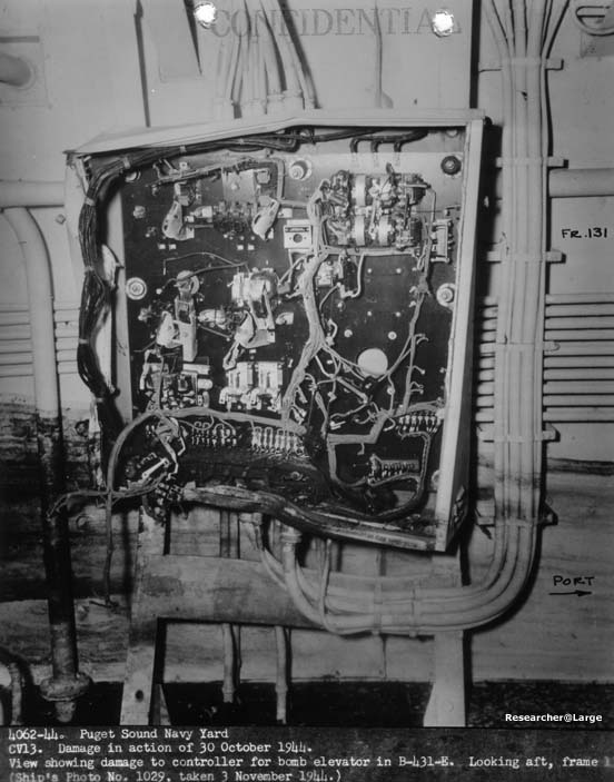
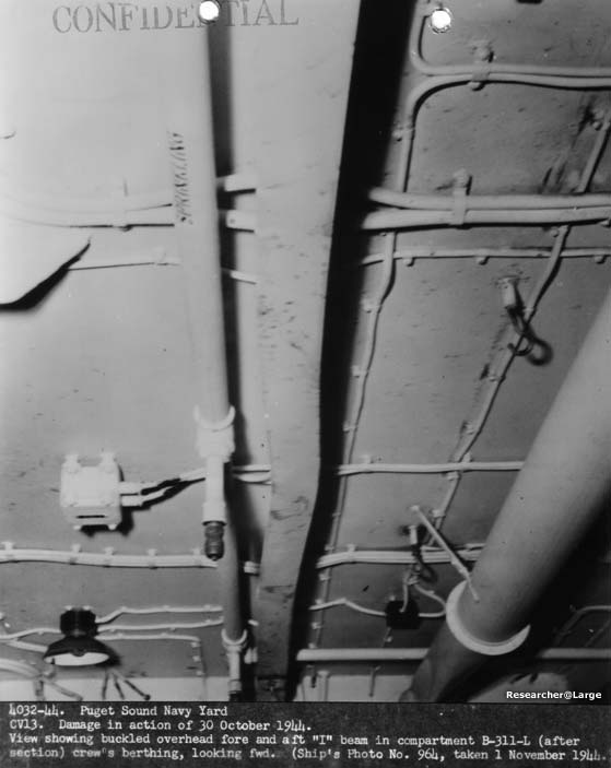
6. Damage to the Fire Control system consisted of the loss of 115 Volts, A.C. supply to the Mk 14 lead at sights of 20mm guns number 23, 25 and 27 through 47, inclusive. This was due to the destruction of the lighting circuits on the Gallery Deck which supply power to these units. The multiple conductor cable containing the elevation, train and gun firung circuits between 5"/38 mount number 7 and the Mk. 51 director was severed by the explosion of the bomb. However, the equivilent circuits to the mount from the plotting room remained intact. 7. The investigation of damage to electrical equipment produced several interesting facts as to the reliability of the equipment. Numerous motors, transformers, fittings, etc., subjected to salt water, although temporarily eliminated from service, were put back into operation after a simple drying process. Many cables, which were burned so that large quantities of outer insulation oozed through the armor braid, continued to carry current and retained a reasonable insulation resistance. Photos Nos. 3995-44, 4027-44, 4032-44, 4033-44, and 4037-44 clearly indicate that electrical equipment, boxes, fittings, cable racks, etc., withstood shock from explosion which was so violent that adjacent and supporting structure were badly distorted. In contrast, however, water was reported in some water-tight connection boxes, presumably due to improperly secured covers.
8. Deficiencies and General Comments.
- 13 -
|
|
WAR DAMAGE REPORT -- U.S.S. FRANKLIN (CV13)
Section VIII Ventilation 1. Damage to ventilation from the hits, fire and salt water, although extensive, was not serious. The damage may be briefly described as follows:
2. Certain systems and equipment suffered damage which may be minimized or prevented through minor design changes. A discussion of the damage and the recommended changes are given below:
- 14 -
|
||||||||||||||||||||||
- 15 -
|
||||||||
|
WAR DAMAGE REPORT -- U.S.S. FRANKLIN (CV13)
Section IX Effect of Flooding from Fire Fighting Water on Stability 1. Acording to reference (a), the displacement at the time of attack was 35,525 tons, and the corresponding GM was assumed to be 9.3 feet, based on the inclining experiment of 19 December 1942. (More recent inclining experiments of this class show that the GM is probably somewhat less.) The ship also reported, via memo from damage control to the first lieutenant, that the following voids were flooded to heights indicated to correct for list:
Flooding of A-32V, A-38V, A-46V, A-48V,and C-10V was not reported in reference (a) apparently because the flooding effect diagram did not show any correction to list for these tanks. It was further stated in reference (a) that the ship listed 3° starboard, as a result of flooding from ship's sprinkling system, and then returned to 2° port after counterflooding had been stopped. 2. Based on this, the maximum probable loss of stability has been computed to compare with the observed behavior of the vessel.
3. In order to make the Flooding Effect Diagram more effective in estimating correction for list for this class of vessel, it is recommended that the angles be recorded to the nearest Ľ° rather than the nearest ˝°. This will aid the ship's personnel in correcting list and prevent unnecessary counterflooding or transfer of liquids. 4. Disposal of large amounts of water from Hangar sprinkling and firefighting activities which accumulate on the Hangar Decks and decks below, has been a serious problem on vessels of this class. To remedy this condition, some steps
- 16 -
|
||||||||||||||||||||
|
have been taken, such as the installation of coamings around certain Hangar Deck hatches and heeling the ship to allow water to run over the side more readily. Puget Sound Navy Yard has installed, at the ship's request, two 8-inch drains in each elevator pit on CV14. While this is not considered entirely satisfactory, it will provide much greater facilities than the existing two 3˝-inch drains. A number of other ideas have been discussed and the following recommendations are made:
- 17 -
|
||||||
|
- 18 -
|
||||||||||||||||||||||||||||||||||||||||||||||||||||||
SOURCE: National Archives & Records Administration, Seattle Branch
Record Group 181, Ship Files ca 1940-1950 514962-73 (62A-140) Box 24
Declassification Review Project NND 958357
Transcribed by Tracy White, who is in awe of the sailors of this ship.
Transcribed by RESEARCHER @ LARGE. Formatting & Comments Copyright R@L.
CV-13 Franklin Kamikaze Attack Home |
Ships Home | Researcher@Large Home