

2-3/4, Starboard
2-1/2, Port
32-3/4, Starboard
62-3/4, Port
155-1/4, Starboard
159, Port
If you can see this text here you should update to a newer web browser
Normal | Highlight & Comment Highlighted Text will be in Yellow
|
CV16/S79-3/90-rec
Serial: 0501 U.S.S. LEXINGTON (CV16) c/o Fleet Post Office, San Francisco, California, 28 August, 1945. C-0-N-F-I-D-E-N-T-I-A-L
1. The trial installation of six caliber .50 Gun mounts, Mark 31 Mod. 0 was completed at the Puget Sound Navy Yard on 13 May 1945. Since the date of installation the mounts have been in regular use and 153,000 rounds have been fired at balloons, TDD, and sleeve targets. No anti-aircraft actions involving enemy aircraft have taken place. 2. Reference (a) requested a report on the operation of the .50 caliber mounts and recommendations as to how they should be used to replace the present 20mm mounts. This report, Enclosure (A), is forwarded herewith. 3. Reference (b) stated that a quad 20mm (N-3) mount had been developed and that installations would commence in the early fall. 4. I fully concur with the plan of substituting multiple-gun power-mounts utilizing belt-fed guns (of not less than 20mm in caliber) with high rates of fire for the present free-swinging 20mm mounts. The Mark 31 mount with certain modifications, as listed in Enclosure (A), would be satisfactory. In view of Reference (b) no additional .50 caliber mounts should be distributed, but a high priority should be placed on the production and distribution of the quad. 20mm M-3 mount when found to be satisfactory. Arrangements should be made to install this new mount on ships now operating with the fleet to replace free swinging 20mm mounts. 5. This report concerns itself with the caliber .50 gun and mount. It is a technical report. It is not an endorsement favoring the installation of small caliber guns with which to fight a ship. A ship should be provided with an arrangment that can consistently destroy a Kamikaze before he gets within the effective range of either the .50 caliber or 20mms.
THOMAS H. ROBBINTS, Jr. Copy To: S??NAV (Office of Research and Inventions).
- 1 -
|
|
CV16/S79-3/90-rec
Serial: 0501 U.S.S. LEXINGTON (CV16) c/o Fleet Post Office, San Francisco, California, 28 August, 1945. C-0-N-F-I-D-E-N-T-I-A-L
CominCh. CNO BuPers. DCNO Air (5) BuShips BuAer CinCPac ComAirPac ComServPac (FMO) ComFairWestCoast Com3rdFleet Com5thFleet ComFirstCarrier T.F. ComSecCarrier T.F. ComTaskForce 38 ComTaskGroup 38.1 ComTaskGroup 38.3 ComTaskGroup 38.4 ComBatPac ComCruPac ComDesPac ComBatSquads All CV's
|
|
U.S.S. LEXINGTON (CV16)
GUNNERY DEPARTMENT 28 August, 1945.
|
|
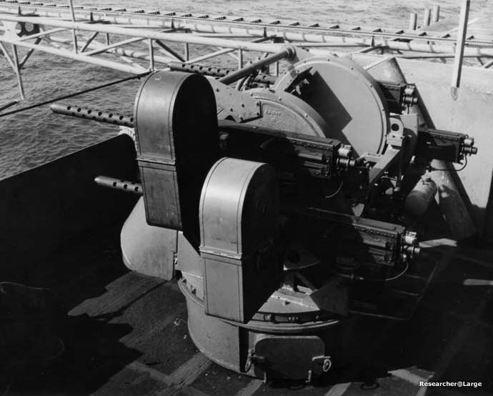
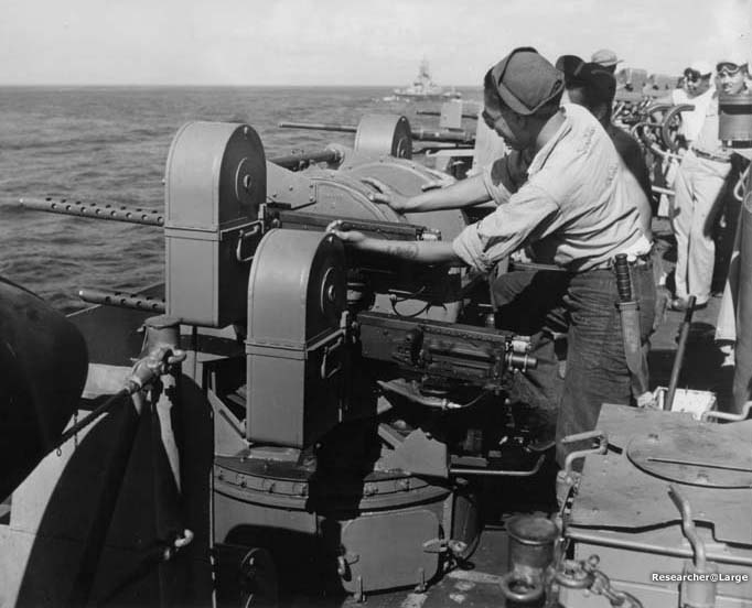
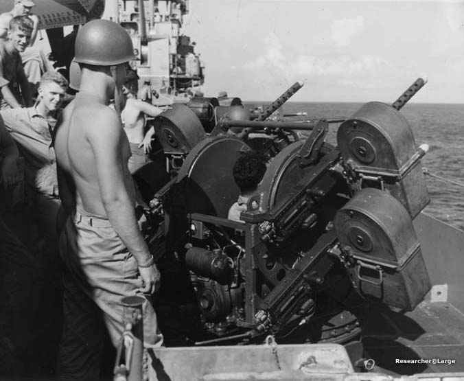
REPORT ON SERVICE EXPERIENCE WITH SIX CALIBER .50 GUN MOUNTS MARK 31 MOD. 0, ABOARD THE U.S.S LEXINGTON.
1. Conclusions and recommendations. A. One quad .50 caliber mount Mark 31. Mod. 0, has the same overall worth as one twin 20mm mount.
B. The advantages of the quad .50 caliber mount, Mark. 31, as compared with the twin 20mm mount are:
C. The disadvantage of the .50 caliber mount, Mark 31 Mod. 0, as compared with the twin 20mm mount arc: D. The Mark 31 mounts require a number of modifications before they would be satistactory for general service use. Most of the difficulties which occured during the first few weeks of operations were due to faulty workmanship or failures of certain parts to withstand the vibration of firing. These faults were correctable aboard ship, but should be corrected in the design of the mount. No failures have occured as a result of corrosion. The batteriesa and gasoline driven generators have perfomed satisfactorily as a source of power.
- 1 -
|
|
E. The utilization of the Cyclic Rate Control Mark 3 was found to be impractical because of the repeated stoppages which resulted from the extractor lug striking or riding over the extractor pivot switch. Better performance and more overall firepower would result from using the .50 caliber gun at the design rate of fire until improved guns with higher rates of fire are available in quantity. Several thousands rounds per gun may accumulate during training excercises between strikes when it is impractical to change all guns or to carry out elaborate preventive maintenance proceduers. The gun performance has been satisfactory since the cyclic rate controls were removed. F. The following general recommendations are made with regards to subsequent developments, trials, and service installations of power operated light machine gun mounts: (1) 0nce it has been thoroughly established from proving round tests that the mount is sufficiently effective and reliable to insta11 on a combatant ship and it is desired to determine its effectiveness the ship(s) selected for the trial should be completely equipped with the new mounts. This would not only reduce the difficulty of maintenance and supply for two types of mounts but would make any increase in effective firepower more apparent. (2) At Least one trained trained gunner's mate, familiar with the mount and the guns should be made available to the trial sbip for each group of four or five mounts installed. This especialiv applies when no shore based training facilities of the type required are available to the ship's personell. (3) If a power operated quad mount employing the 20mm automatic gun M-3 were used, the increased firepower wouid permit greater spacing between mounts with a resulting decrease in smoke interfernce. Where time and facilities permitted the gallery groups could be completely rearranged to provide a separete circular p1atform, a battle telephone, and a ready service ammunition locker for each unit. Such an arrangement would result in greater angular coverage for mount, better visibility, and less interferance between personell reloading the guns and passing the ammunition. Additional mounts should be located on the island structure, on the fantail and, if possible, on platforms suspended from each cornerr of the flight deck to provide greater firepower in areas most vulnerable to attack. (4) It is recommended that new types of mounts be equipped with fixed reticle illuminated gunsights with speed rings which may he interpeted in hundreds of knots based on the time of flight of the projectile to 1000 yards, until a computing sight can be developed. The gunsight should be mounted in a shock proof mount to prevent blurring of the reticle image and to increase bulb life. A computing sight should be developed with high priority. (5 ) It is suggested that an aided tracking power unit be developed for use in future mounts. It should be possible to remove and replace the power unit without removing the entire mount from its foundration. (6) No further installation of this power mount should be made until 20mm guns replace the .50 caliber guns. It is requested that facilities be provided for conversion of the LEXINGTON mounts as soon as practical. (7) The quadruple 20mm mount should replace two twin 20mm mounts or four single 20mm mounts.
- 2 -
|
|
2. Material. A. All of the material listed in Enclosure (a) "Assembly list of Ordnance Material" of Bu0rd ltr. CV-16 (Ad7b) dated 10 May 1945 was eventually received with the exception of the mount tools and Electric Trigger Controls. The Electric Trigger Controls were shipped folloving a dispatch request from the LEXINGTON. (instruction manuals, blueprints, a list of material shipments, and much of the actual material for the LEXINGTON installation were received by the ship several days after the scheduled sailing date and after the mounts had been installed and test fired.) B. Most of the spare parts included in the Mark 31 Mod. 0 allowance list, NAVORD LIST NO. 21522, dated April 9, 1945, were not and are not available to the ship. When this material is made available the ships concerned should be notified.
NAVORD LIST NO. 21522 is made out on a "per mount" basis which is satisfactory where only small numbers of mounts are installed on each ship. If a large number of mounts were used it would be high on spare assemblies such as the drive and power charger units and low on wearable and breakable parts such as piston rings, valves, pulleys, etc. It is suggested that a column B list based on a group of mounts be made up to include complete spare assemblies and that the column A list be revised accordingly. It is further recommended that one complete mount be supplied to each ship for training and emergency replacement. (One mount was destroyed on the LEXINTON as a result of an airplane crash during routine landing operations. There was no replacement .50 caliber mount available.) The fo11ing comments are made in conection a11owance lists, NAVORD LISTs NOS. 21521 and 21522: |
|
D. Because of the many improvements and modifications of the origina1 .50 caliber machine gun it would be highly desirable if only guns of recent manufacture were made available for these mounts. It is also recommended that only guns in moistture proof wrappings be provided. Degreasing a large number of guns is very difficult to do on board ship especially if guns have to be made ready for use a short time after they are drawn. E. A complete set of instructions and an assearibly list of should be made available to the ship and the yard where the mounts are to be installed as early as possible and preferably two weeks in advance. F. The following miscellaneous items were obtained from Naval Supply Depots or other sources and were found usefull in maintaining and opererating the mounts:
A. The installation of the six quad .50 caliber mounts by the Puget Sound Navy Yard was completed on 13 May 1945. This included the installation of the adapters, mounts and the cutting of the firing interruptor cams. The insta11ation and boresighting of the machine guns was carried out by ship's personnel. The 10" mount stand was left in place between the mount and the adapter for the fol1owing reasons:
- 4 -
|
|
2Omm twin when cutting the cams. This permits a train angle of 59º away from the beam toward the adjoining mount. The elevation axis must be at least 481/2" above the deck if the shield is to be cleared at this maximum
firing angle*. It is 491/2" with the stand and 391/2" with the stand removed.
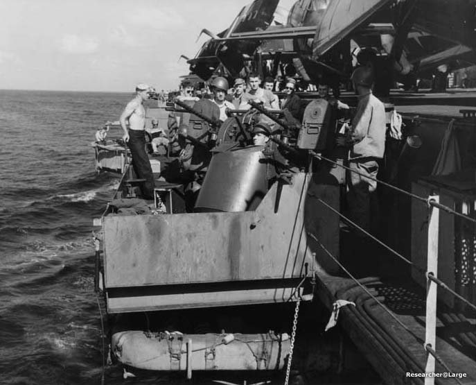
B. The mounts were all located on the gallery walkways as shown in the attached photographs. (The stands are removed in the photographs.) The locations of the mounts are given below:
C. The average unrestricted firing angle in train of each mount is 110º, about 60º measured from the beam toward the adjacent 20mm mount in the sponson and 50º from the bean in the opposite direction. The latter angle is 1imited by the raised section in the splinter shield.
- 5 -
|
||||||||||||||||||||||||||||||||||||||||||
|
F. Mounts were damaged on two occasions as, a result of air operations. (1) on 6 June 1945 Mount No. 5, Ser. 61805, was covered with flaming gasoline, foamite, and salt water as a result of an airplane crash on the flight deck. The mount cover was burned and throvn overboard. The gunsight and firing solenoid wire insulation was slightly damaged but the mount remained operative. No serrious damage resulted. (2), On 8 July 1945 Mount No. 6, Ser. 61790 was damaged beyond repair when an aircraft crashed on the gun sponson during landing operations. The mount was removed and stripped of usable parts for spares. A twin 20mm mount was installed in its place. Useful note for modelers! See the photo of Mount six below if you need help figuring out where this was. 4. Recommendations on Group Arrangement.
Although it is not anticipated that additional quad .50 caliber mounts, Mk. 31, will be distributed, the following recommendations are made with regard to group arrangment as they apply to some extent to any multiple-gun power-mount: * Note: Sixty inches would be a minimum radius.
(2) A practical arrangement would be to replace two twin mounts with one quad 20mm power mount.
- 6 -
|
|
This arrangement would also permit the installation of two 60" X 30" work benches in each room, i.e. one for each mount operator.
A. Mount casualties. The following is a summary of the mechanical and electrical failures which have occurred on the mounts sinco they were installed. Many of the items were of an easily corractable nature. Only a small number of the failures caused the mounts to become inoperative during firing practices.
B. Changes in design aboard ship.
The following is a summary of the changes which were found necessary and which were made aboard this vessel:
- 7 -
|
|
(7) Voltmeters were removed as they did not serve to give a reliable indication of the remaining energy in the batteries and would not withstand the vibration of firing.
C. Essential modifications. The following modifications are essential to the succesful operation of the mounts:
D. Modificaticns applicable to future models. Future models of this mount should be redesigned with an emphasis placed on increasing the safety factcrs on all parts where necessary, especially in the drive system.
|
|
the following list contains recommended changes applicable to future Marks or models. (1) A mechanical contour cam device for prohibiting the gunner from training the mount into restrictect areas should be provided. This would greatly increase the coverage of the mount, especially when it is mounted in a gallery, group. It would afford more protection to personnel on adjoining guns when "cook-offs" are likely. (2) The leather dust shield for the azimuth ring gear should be held in place with metal strips provided with metal "fingers" to insure a good seal. (3) A dead-man switch would reduce the operating time of the mount and the charger. "Idling" of the power drive unit would then require a conscious effort on the part of the operator. (4) The present V-belt pulleys are easily bent or damaged. They should be of solid construction and securely fastened to the pulley shafts. A slight inclination of a pulley results in a tendency for the mount to drift. (5) The V-belt drive differential adjusting slots should be lengthened to permit further tightening of the V-belts. If a separate cover for the slots held in place by scews were used it would be unnecessary to remove the large cover plates (BuOrd 506967) which make's V-belt adjustment a major item in maintenance. (6) A spring loaded zero-centering adjusternent device mountcd on the gear support lever would facilitate a corrective measure for drift. Elevation drift to some degree was present in all mounts and could not be completly removed. (7) A square spline shaft to replace the present involute spline would strengthen the power drive system. (8) A two cycle power charger of 60-90 ampere capacity is reccomended. If a charger of this capacity were used, switching from the "low" to the "high" connections on the generator field windings should be accomplished by a relay operating from the drive motor circuit. Such an arrangement wou1d insure a maximum charging rate when the mount was operating but would prevent overcharging and overheating of the cells. (If ship's power were used as the main source of energy and a motor-generator or dry rectifier were used it would be advantageous to retain the batteries as an emergency source of power). (9) An electric charging mechanism for the guns or an electrically operated device for holding the bolt to the rear would facilitate more rapid cooling and e1iminate the ever present danger of a personnel casualty from a "cook-off" or from the explosion of a hot round which has been removed from the gun. (l0) Although the back plain solenoids have been satisfactory it is believed that a top plate or side plate solenoid would be preferable for obtaining more accurrate timing. (ll) A thicker and stronger gasket should be used on the inner trunnion cover. A better seal would be provided if a stiffener ring were used between the screws. (12) The indicator lamps and motor thermostat are believed superfluous and unnecessary. Their removal would simplify the wiring arrangement. (13) A special wrench should be provided for turning the boresight handwheels which cannot, in most cases, be turned by hand. A redesign of the mountings to permit the use of an ordinary large end wrench would be desirable. (14) Manual triggers on the guns are easily broken and are believed to be unnecessary.
- 9 -
|
|
(15) A sheet metal heat insulator should be provided between the gunner's back and the power charger unit. (16) The armor shield should be enlarged to provide more footroom when entering and vacating the mount. More knee room should also be provided. Constant rubbing of the knees against the armor shield becomes painful when the operators must remain in the mounts for long periods of time. (17) The mounting holes on the azirnuth ring gear should be radially slotted to permit the insertion of the mounting bolts without disconnecting the azimuth pinion shaft ang rotating the mount. A slightly 1arger bolt circle would accomplish the same purpose. (18) A redesign of the sight and mount cover is recommended. A loose light weight cylindrically shaped mount cover with a strong tie rope threaded through a hem at the bottom is recommended. The N.G.F. power charger cover and frame modification (BuOrd Dwgs. 506966 and 506969) were found to be very satisfactory. It is believed that if a quickly removable and replace-able mount cover were supplied the other protective covers would be unnecessary. (19) A permanent metal splash cover should be provided for the exposed generator windings. (20) An easily removable electric aided-tracking power unit should be developed to replace the V-belt unit. A. Rounds fired. Between 14 May 1945 and 24 August 1945 153,000 rounds of 0.50 caliber ammunition were fired on thirty-nine firing days. Not a11 mounts fired on every firing day. B. Quality of guns. Most of the guns received in the initial shipment were guns of old manufacture. There was evidence of wear in some of the guns which had been presumably reworked. The guns were changed on 25 June 1945 when almost 100,000 rounds naa been fired from the 24 guns. Relatively new guns were used to replace the old guns. C. Removal of Cyclic Rate Controls. No Cyclic Rate Controls were installed on the new guns on 25 June 1945. The chief reason for the non-use of the rate controls on the new guns was the increasing number of stoppages which had occurrcd as a result of the extractor lug burring or riding over the pivot switch on counter-recoil on the first installation of the guns. D. Casualties. The following is a partial list of gun casualties which had occurred up to 21 July 1945. Nearly all of the casualties with the exception of the barrel explosions occurred on the initial installation of guns, prior to 25 June 1945. The list is by no means complete. It will however reflect to some extent the type and relative frequency of certain casualties.
- 10 -
|
||||||||||||||||||
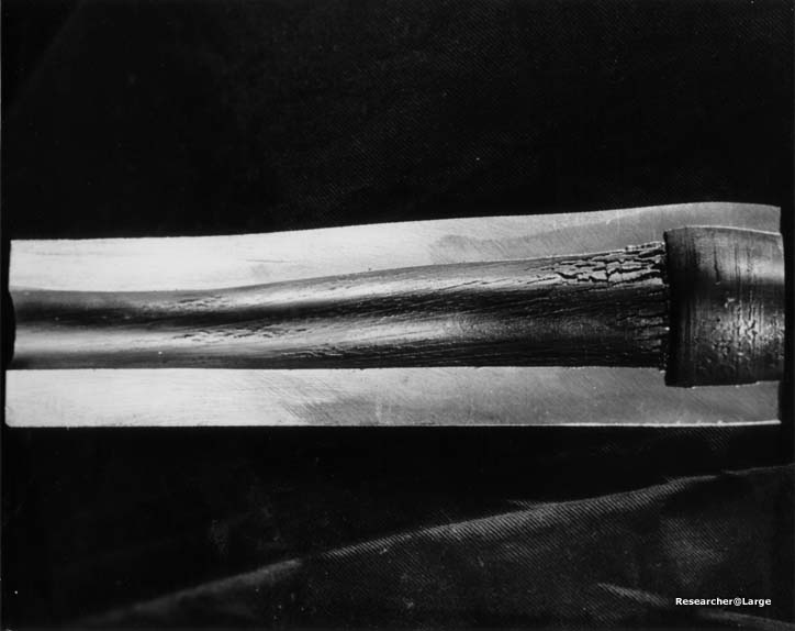
E. Barrel life. No accurate data has been obtained with regard to the barrel life of the special barrels under service conditions. The barrels have received severe treatment because of the frequent anti-aircraft practices. Gunners have not only been encouraged but have been instructed to shoot continuously when the target is in range. Two hundred round bursts have been fired frequently and often in succession. The following table of four exploded and two "swollen" barrels* indicates that the barrcls will not withstand three chests or 600 rounds in succession, even when new, unless some anpreciable cooling period is allowed between bursts.
* Note: A cross section photograph image of one of the swollen barrels is attached herewith. The average barrel life is estimted at 5,000 rounds, whereas the life of an individual barrel might vary frcm 600 rounds to well over 5,000 rounds depending on the number of rounds fired with the barrel above the critical temperature and the maximum firing temperatures reached. The guns were equipped with standard barrels prior to 1 June 1945. These barrels were used to conserve the special barrels during the initial training period. The projectiles began to tumble after 1000 rounds had been fired from the standard barrels.
F. Personnel Casualties. The most common personnel errors were: An officer on temporary duty from the Special Devices Division of the Office of Research and Invention, Lt. E.V. Hardway, USNR, was (and is) of greatest assistance in the installation details, maintenance, and the training of the gunners and loaders. He was ably assisted during the first six weeks by Army Private (formerly a civilian technician), Gordon Anderson, Pfc. U.S. Army Air Corps.
- 11 -
|
||||||||||||||||||||||||||||||||||||||||||||||
|
No ship's company officers or men had previous experience with this mount and installation and training would have been
very difficult without the services of these specialists.
B. The four forward mounts were manned by strikers and loaders of the 5th (forward l.m.g.) division with a gunner's mate second class in charge of maintenance. The after mounts were manned by privates of the 6th (after l.m.g.) division. The wide dispersion of the mounts about the ship among six different groups made training and evaluation of results several times more difficult than it would have been if the mounts had been grouped together. Insufficient mounts were installed to warrant forming a new division. C. The initial training consisted of lectures and the showing of training films and slide films during both day and evening periods. This trainig carried on at the end of a Navy Yard overhaul period was under very trying conditions, due to loading ship, inspecting installation of material, and cleaning ship. During the first six weeks anti-aircraft firing exercises were conducted almost daily. The men thus received considerable training through experience and informal instruction in tracking, firing, gun cleaning, mount maintenance, etc.. This training would have been far more efficient if more time had been available for analysis. Training accomplished on board durirg the first six weeks could have been accomplished in a much less time at a shore based school, with adequate facilities. Every effort should be made to train men on shore, for a new type mount, before the men are ordered for duty with the mount. D. A marked improvement resulted after a program of routine maintenance was commenced. This consisted of daily inspection "Check-Offs" by the mount operators, weekly and monthly inspections by the gunner's mate and gunnery sergeant in charge and frequent random inspections by the responsible officer. A record of inspection, rounds fired, casualties, mount history, etc. is being kept in a gunnery office log. The mount operators turn in a report of rounds fired through each barrel and gun and mount casualties after each firing exercise. E. One loader was injured as a result of violating the safety precautions. Six hundred rounds had been fired through each barrel in a re1atively short time. The guns were unloaded immediately after the firing run. Orders were then given to stand by for another firing run. As a result the guns were reloaded and the target was tracked but "commence firing" was not given. The left loader then unloaded the guns and picked the unexploded cartridge up to throw it over the side. It exploded in his hand causing burns on his hand and ankle about two seconds after it was ejected. The loaders had been previously warned to leave the gun loaded in such a case but to clear the chamber immediately after the first "cook-off." The loaders are required to clear the chamber immediately after each firing run. (This was done in the above case but the guns were reloaded a few seconds afterwards.) It is believed that it will be very difficult to entirely prevent such personnel casua1ties on a ship fully equipped with Mark 31 mounts unless some means is provided for holding the bolt to the rear automatically. F. If a quad 20mm (M-3) mount is to be used it is recommended that a gunner's mate - mount operator with at least 2 to 3 weeks of specialized training ashore to placed in charge of each mount. At least four men, one or two being strikers, should be used for loaders. At least one specially trained gunner's mate for each group of four or five mounts should be made available to any ship chosen for a trial installation.
- l2 -
|
|
G. In the event that sufficient facilites are not available at AATC's for conducting training courses in the quad .50 caliber or 20mm mount, it is suggested that arrangements be made for utilizing the facilities of the Naval Air Gunner's Schools and Combat Aircrewman Training Units.
F:. Inspection "Check Off 11 list.
|
||||||||||||||||||||||||||||||||||||||||||||||||||||||||||||||||||||||||||||
|
|
|
| Mount 1, Frame 2-3/4, Starboard |
Mount 2, Frame 2-1/2, Port |
Mount 3, Frame 32-3/4, Starboard |
|
|
|
| Mount 4, Frame 62-3/4, Port |
Mount 5, Frame 155-1/4, Starboard |
Mount 6, Frame 159, Port |
|
||
| Swollen .50 Caliber Barrel mentioned in section 1, C. (2) | ||
Transcribed by RESEARCHER @ LARGE. Formatting & Comments Copyright R@L.