

If you can see this text here you should update to a newer web browser
Normal | Highlight & Comment Highlighted Text will be in Yellow, but there are none yet
|
RESTRICTED
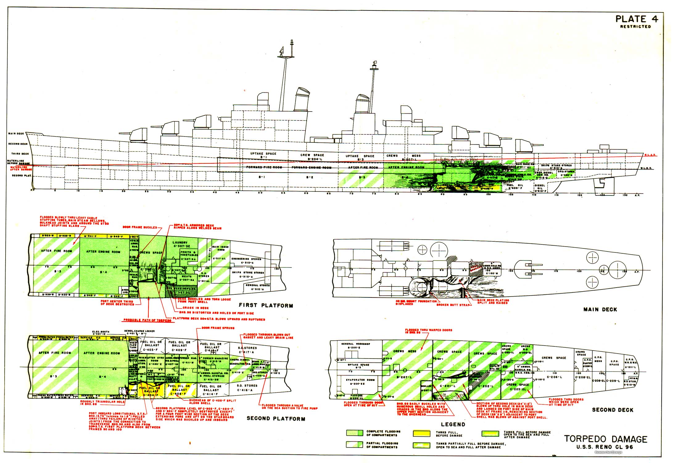
1. A submarine torpedo detonated at about frame 92, port, in way of shell strake "C", and caused serious local damage. Shell plating and supporting structure was ruptured between frames 88 and 97, a distance of about 33 feet, and from "B" strake to "F" strake, a distance of about 22 feet. Damage to adjacent plating extended between frames 84 and 103 and from "A" strake to the main deck. The main, 2nd and lst platform decks were destroyed between frames 88 and 97, port. This damage as well as that to the main deck and interior structure is shown on Plate 4 and Photos 2 and 3. Extensive flooding resulted in a condition of negative initial stability, however, damage control measures undertaken by the ship's force and ZUNI (ATF 95) enabled the ship to be towed 700 miles to Ulithi. Despite the marked loss of strength at frame 93, port, no progressive structural failures were noted during this passage in heavy weather. 2. No drydoaking facilities were available at Ulithi. Temporary repairs were undertaken by VESTAL (AR 4) and RENO with the aim of making the best possible improvement in stability, watertight integrity, and longitudinal, transverse and local strength. Immediately upon arrival and throughout repairs divers were used to determine the extent of damage, both in the vicinity of the explosion and to the rest of the underwater body and appurtenances. a. Stability During Repairs (Refer to Plate 4).
|
|
RESTRICTED
|
||||||||||||||||||||||||||
|
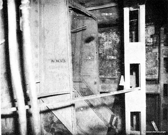
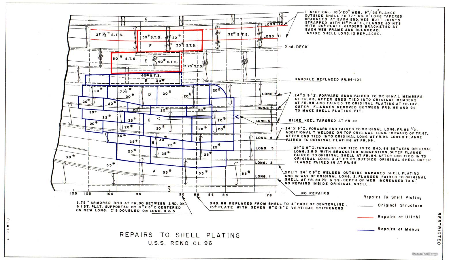
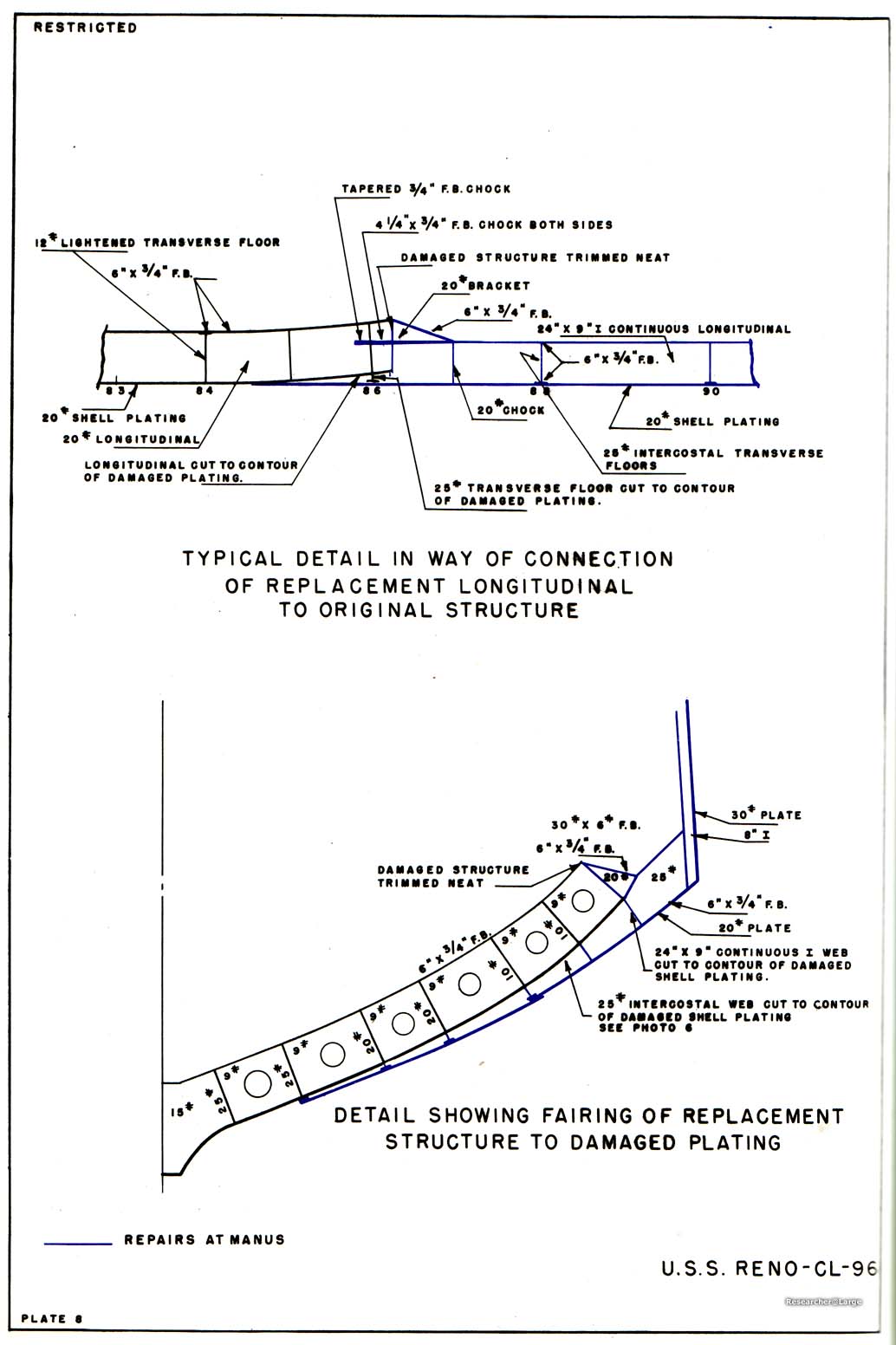
3. After completion of these repairs, RENO was towed to Manus and drydocked in AHSD 2, where temporary repairs to the underwater body were made by WHITNEY (AD4), Navy Repair Unit 3205 and RENO. The care taken to align replacement members with original structure and to achieve continuity in way of all connections is shown in Plates 7, 8 and Photos 6, 7. Stanchions were installed at frames 90, 92 and 94 1/2 to compensate for the bulkhead which was not replaced at frame 90 and to provide additional stiffness (Photo 8).
|
|
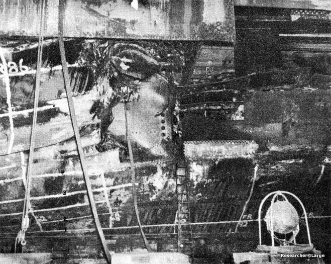
Photo 2: RENO (CL 96) Damage, frames 86-94. Note intact 3.75" STS plating. |
|
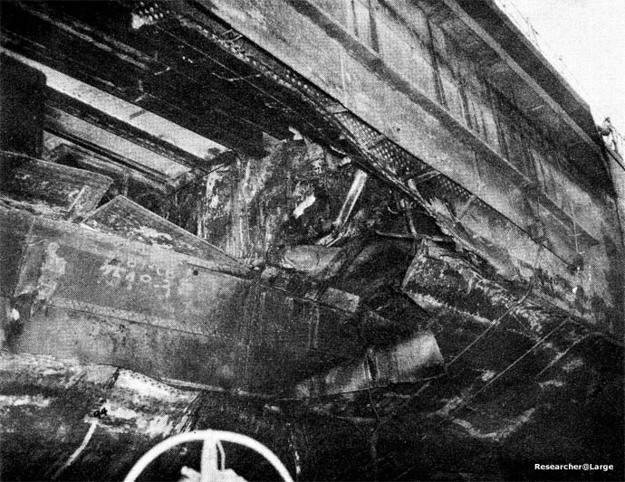
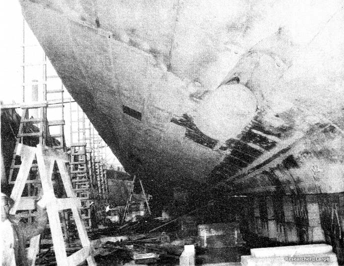
Photo 3: RENO (CL 96) Looking aft at underwater damage, frames 93-103. Note above water repairs made at Ulithi. |
|
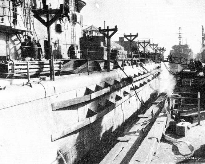
Photo 4: RENO (CL 96) Looking aft at logitudinal strengthening members on shell and main deck. |
|
Photo 5: RENO (CL 96) Looking to port and aft showing replacement structure. |
|
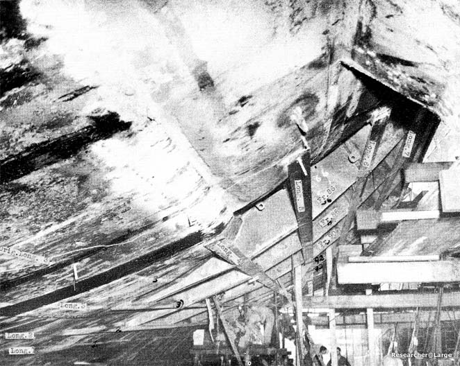
Photo 6: RENO (CL 96) Fairing of longitudinals and transverse frames to undamaged original structure. |
|
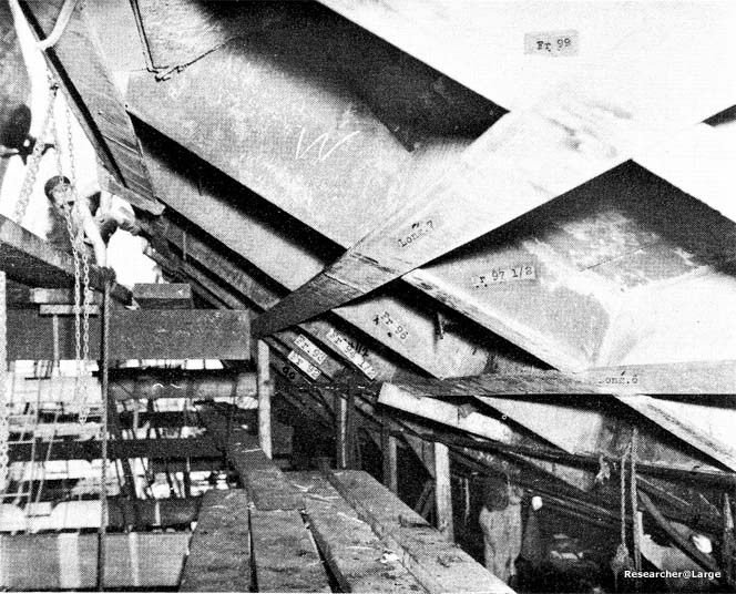
Photo 7: RENO (CL 96) Looking forward from frame 99. Showing method of fitting continuous longitudinals and intercoastal transverse floors outside damaged shell plating. |
|
Photo 8: RENO (CL 96) Interior repairs. Note deep frames 92 and 94 1/2 at shell; columns fabricated from double 8" x 3" channels supporting 2nd deck, columns supporting armored bhd. 90, and deep longitudinals with bracketed end connections under 2nd deck. |
|
Photo 9: RENO (CL 96) Looking forward at after end of replacement plating. Note watertight seal on port stern tube. |
|
Plate 4: Diagram of torpedo damage to hull and structures. |
|
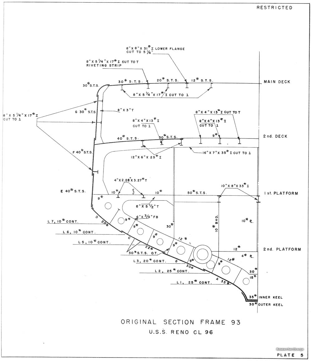
Plate 5: Frame 93 structure before damage. |
|
Plate 6: diagram of structural reinforcement and plating in area of damage performed in forward area. |
|
Plate 7: Repairs to shell plating, frames 80-105 |
|
Plate 8: Shell plating repair performed at Manus. |
| The Below photos were not included with the original report but are provided for additional reference | |
|---|---|
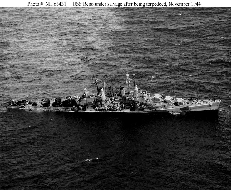 |
NH 63431: November 5th, 1944; two days after the torpedo hit. Fleet Tug Zuni ATF-95 is alongside to port rendering assistance. Note the fuel oil streaming from the aft end of the ship |
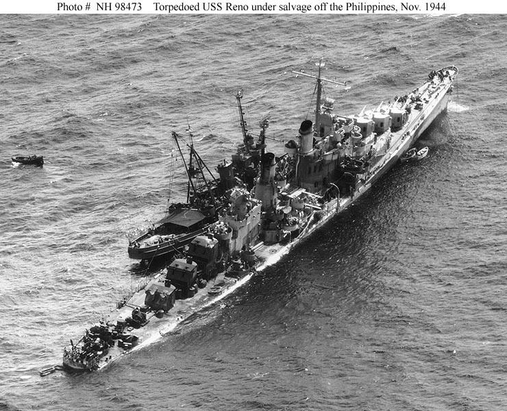 |
NH98473: Also photographed on November 5th, this photograph visible shows how close to capsizing Reno was |
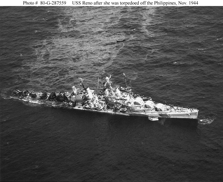 |
80-G-287559: Another shot highlighting the fuel oil streaming from the ship. Note also that some work to increase her stability has been done as the starboard side torpedo tubes have been jettisoned. |
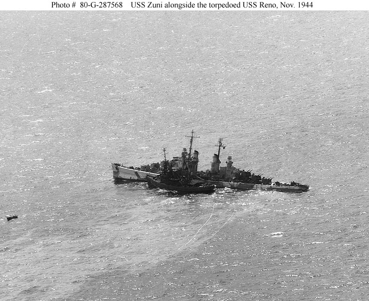 |
80-G-287568: Another photograph showing Zuni alongside |
Transcribed by RESEARCHER @ LARGE. Formatting & Comments Copyright R@L.
Reno Home | Repairs in Forward Areas Home |
Ships Home | Researcher@Large Home