


If you can see this text here you should update to a newer web browser
Normal | Highlight & Comment Highlighted Text will be in Yellow, but there are none yet
|
RESTRICTED
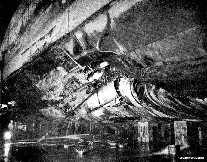
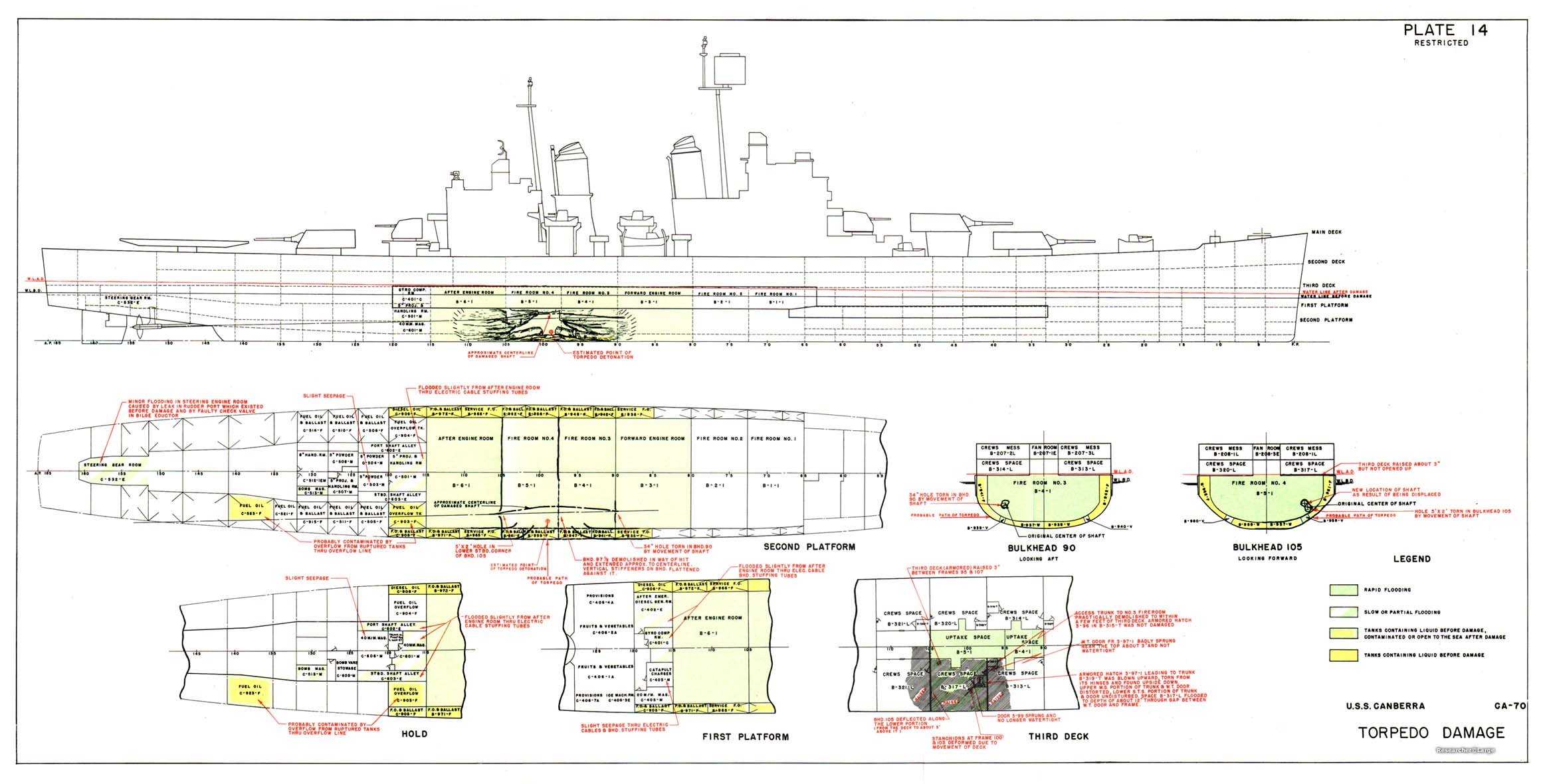
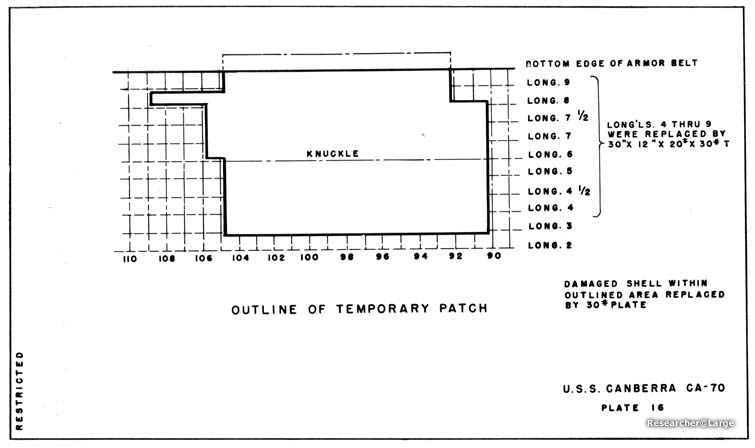
1. While participating in carrier strikes against targets in Formosa, CANBERRA was damaged by an aircraft torpedo that exploded at frame 99, starboard, about 18 feet below the waterline. Damage to the hull was of the same order of magnitude as that observed in other U. S. cruisers damaged by torpedoes. The side and bottom plating was ruptured from frame 95 to frame 104, starboard, and from 15 feet outboard of the keel up to the armor belt. Firerooms 3 and 4 flooded instantly. The starboard half of bulkhead 97 1/2 was blown forward with the lower portion pushed upward against the first platform in fireroom 3. No. 1 shaft was bent upward and inward in a long radius curve and tore large holes in bulkheads 90 and 105, which were not otherwise damaged by blast or fragments. This resulted in rapid flooding of engine rooms 1 and 2 (Plate 14, Photos 25 and 26). All propulsive power was lost. CANBERRA was taken under tow and on 27 October arrived at TTlithi, a distance of 1400 miles. 2. During the period 17 to 28 October, 138 hours of diving operations were conducted to determine the extent of damage to the forward engine room, to isolate piping systems, and to restore the watertightness of bulkhead 90, the after bulkhead of the space. Divers established that the principal source of flooding was through a 36-inch diameter hole in way of No. 1 shaft. The damaged shaft bulkhead gland was removed, as were the shaft revolution counter gear box and its foundation, the sheet metal guard for a shaft coupling, and electric cables in the vicinity of the hole. Then an electric underwater cutting torch was used to trim the jagged edges of the hole in the bulkhead. When this preparatory work had been completed, a patch was fitted around the shaft and covering the hole. This patch was made in two sections from 15 pound plate. It was bolted through the bulkhead and seated on a 1/4 inch rubber gasket. After this patch had been installed, 15 hours of pumping were required to bring the water level down to mid-height in the compartment, a depth of about 12 feet. The upper half of the bulkhead was then shored. After this shoring was completed, pumping was resumed.
|
|
RESTRICTED
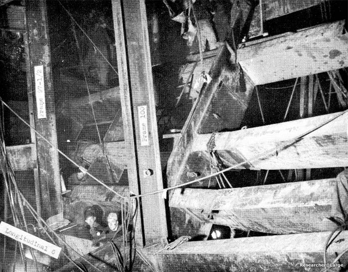
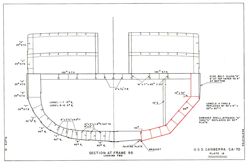
As the waterlevel receded, additional shoring was installed and small leaks were plugged as they became apparent. Upon completion of these and other minor repairs, CANBERRA was towed to Manus, where dr~,docking facilities were available, for additional repairs; arriving, there on 17 November. 3. At Manus, CANBERRA was drydocked in ABSD 2 for unwatering of the remaining flooded spaces and temporary repairs to the underwater body. Inspection indicated that the keel was deflected inward between frames 94 and 105; the maximum being 2 3/4 inches at frame 99. Longitudinals 1 and 2 were hogged and slightly wrinkled between frames 90 and 105. Longitudinal 3 was partially fractured at frame 99 and bent between frames 90 and 105. Longitudinals 4, 4 1/2, 5, 6, 7, 8 and 9 were ruptured and bent between frames 90 and 105. Longitudinal 10 was partially ruptured and bent between frames 95 and 102. All transverse frames in way of the damaged longitudinals were distorted and required replacing. Shell plating was ruptured and bent in the damaged area. 4. Hull repairs were planned to restore the original strength in the simplest manner (Plates 15 and 16). Flat plates were used whenever possible with a knuckle installed at longitudinal 6. Plates at the forward and after ends of the patch were shaped to make a fair transition between the flat plates and the original shell. 5. After removal of the damaged hull structure (Photos 27 and 28) and machinery, replacement longitudinals were installed.
6. Other repairs were:
|
||||||||||||||||||||
|
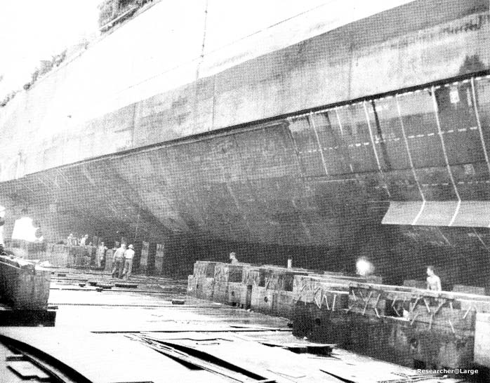
7. Exterior views of the completed repairs to the shell are shown in Photo 31.
|
||||||||||||||||||||||||||
|
Photo 25: CANBERRA (CA 70) Looking forward at torpedo damage. |
|
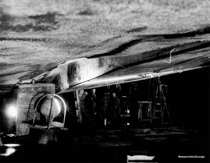
Photo 26: CANBERRA (CA 70) Looking aft at torpedo damage. |
|
Photo 27: CANBERRA (CA 70) Looking forward at torpedo hole after removal of damaged structure. |
|
Photo 28: CANBERRA (CA 70) Looking aft at torpedo hole after removal of damaged structure. |
|
Photo 29: CANBERRA (CA 70) Replacement longitudinal 3, extending outside shell in way of buckled portion of B strake. |
|
Photo 30: CANBERRA (CA 70) Longitudinal and transverse framing; stanchions in way of knuckle at longitudinal 6. |
|
Photo 31: CANBERRA (CA 70) Looking aft at completed repairs to underwater body. |
|
Plate 14: USS CANBERRA (CA 70) Torpedo Damage |
|
Plate 15: USS CANBERRA (CA 70) Section at Frame 95, Looking Forward |
|
Plate 16: USS CANBERRA (CA 70) Outline of Temporary Patch |
SOURCE:
Transcribed by RESEARCHER @ LARGE. Formatting & Comments Copyright R@L.
Canberra Home | Repairs in Forward Areas Home |
Ships Home | Researcher@Large Home